Livox device time synchronization(livox设备时间同步说明中文文档)
1 Time synchronization instructions
Livox devices support 3 time synchronization methods:
PTP: IEEE 1588v2.0 PTP network protocol synchronization;
GPS: Pulse per second + GPRMC time data, forming a GPS time synchronization method;
PPS: Pulse synchronization per second, requires the upper application program to obtain the time information of each pulse through other channels (such as uart) and correct the point cloud time. At present, only LiDAR supports this synchronization method, and because the usage is relatively complicated, it is not recommended for users to use this method for LiDAR time synchronization.
Synchronization methods supported by different devices:
| Devices | Supported synchronization method |
|---|---|
| Livox LiDAR | 1. PTP v2 2. GPS 3. PPS(not recommanded) |
| Livox Hub | 1. PTP v2 2. GPS |
1.1 Synchronization principle
1.1.1 PTP time synchronization principle
The synchronization process uses the Delay request-response mechanism (two steps) of IEEE 1588v2.0 PTP. The Livox device acts as the slave and synchronizes the PTP time with the master clock device.
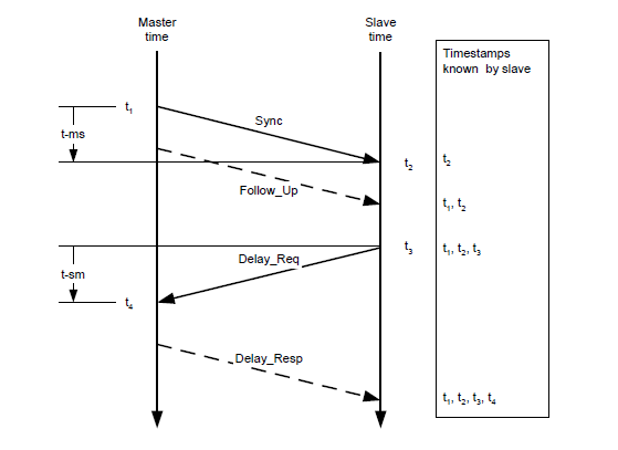
The master and slave clocks obtain the t1, t2, t3, and t4 time through the interaction of Sync, Follow_Up, Delay_Req, Delay_Resp these data packets, and the transmission path delay and the offset of the two clocks are calculated as follows:
Transmission path delay: Delay = [(t4 – t1) – (t3 – t2)]/2
Time offset: Offset = (t2 - t1) - Delay = [(t2 – t1) + (t3 – t4)]/2
1.1.2 GPS time synchronization principle
The PPS port of the GPS clock source sends a hardware pulse (PPS signal) once per second, and then the data port sends the time information corresponding to the rising edge of this pulse (GPRMC format) once.
After the Livox device receives the rising edge of the PPS signal and parses the correct time information from the GPRMC data, it will set the point cloud time as the GPS time, and keep this time reference for continuous accumulation to achieve time synchronization with the GPS device.
-
Livox Hub can directly receive RS485 level GPRMC signal;
-
Livox LiDAR cannot directly receive GPRMC signals, it needs to connect the GPRMC data port to the PC, and then send it to the LiDAR through the SDK protocol;
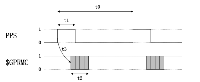
The timing requirements of PPS signal and GPRMC signal:
| Time | Description | Effective Range | Recommended Value |
|---|---|---|---|
| t0 | Interval between rising edges of adjacent twice second pulse | 900 ms ~ 1100 ms | 1000 ms |
| t1 | High level time of each second pulse | 5 ms ~ 900 ms | 10 ms ~ 200 ms |
| t2 | GGPRMC transmission time (baud rate: 9600bps) | ≈ 70 ms | 70 ms |
| t3 | The delay of GPRMC data transmission relative to the rising edge of the pulse | 0 ms ~ 900 ms | 0 ms ~ 430 ms |
1.2 Application scenario
PTP:
In the absence of GPS and PPS hardware signals, PTP v2 can be used for time synchronization between Livox LiDAR/Hub and other devices. This method requires minimal external hardware support, and only requires a master clock device in the entire network.
GPS:
This synchronization method can be used when Livox Hub is connected to multiple LiDARs. Livox Hub needs to be connected to the PPS signal of the GPS receiver and the time signal in GPRMC format. At this time, the LiDAR point cloud time will be automatically corrected to the GPS time.
Livox LiDAR can also use GPS synchronization, but it needs to connect the GPRMC signal to the PC, and then send the time data to the LiDAR through the SDK protocol.
2 Instructions of use
2.1 PTP
When Livox LiDAR or Hub is connected to a network with a ptp master clock, the device will automatically synchronize its time to the master clock.
2.1.1 Configuration and use
Step one: Check whether the master clock in the network is normal
For the method of configuring the master clock on the PC, please refer to the appendix Configuring the PTP master clock;
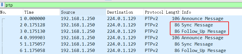
If there are datas of Sync and Follow_Up in the network, it means that the PTP master clock source is working normally:
Step 2: Connect Livox LiDAR/Hub
Livox LiDAR/Hub can be connected normally through the network cable, no additional wiring is required.
Step 3: How to check the device is using PTP 1588 synchronization
1、By checking the timestamp_type data in the point cloud data packet header, the point cloud data protocol: https://github.com/Livox-SDK/Livox-SDK/wiki/Livox-SDK-Communication-Protocol
If timestamp_type is 1, it means that the device is performing PTP time synchronization:
| timestamp_type | data_type | timestamp type |
|---|---|---|
| 1 | uint64_t | Nanosecond(ns) |
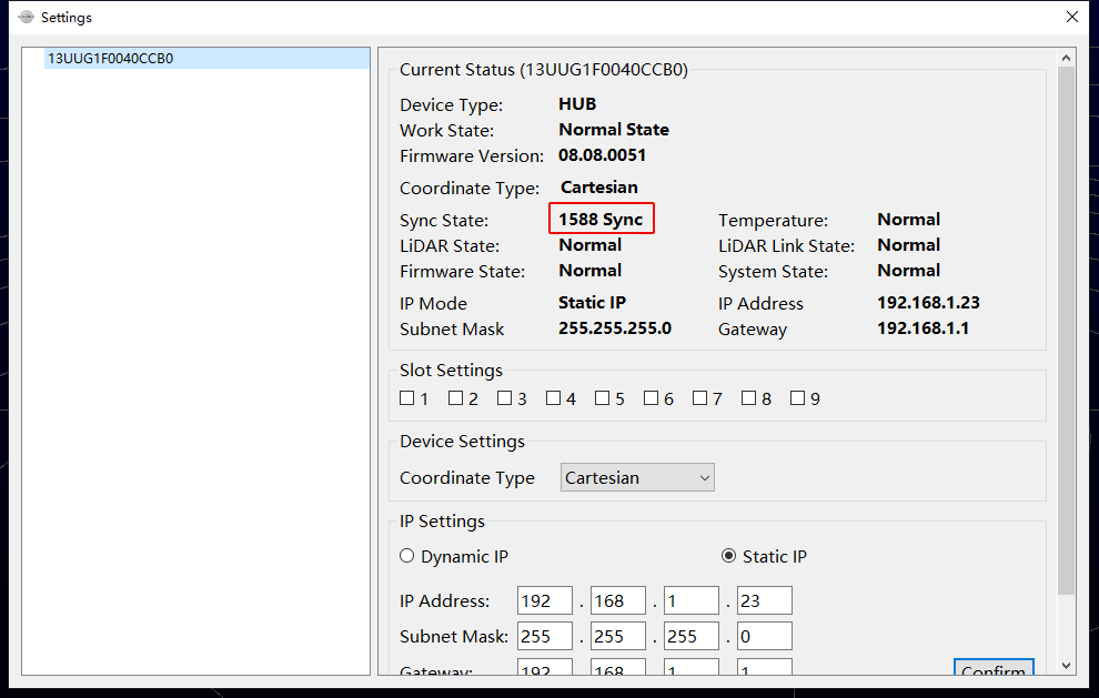
2、Or check the Settings option in the Livox Viewer host computer, the Sync State in the figure below indicates that the Hub is using ptp 1588 synchronization.
2.1.2 Precautions
- PTP synchronization has the highest priority. When PTP, PPS or GPS are available at the same time, PTP network synchronization will be selected priority;
- Does not support network environments with multiple master clocks;
- Hundred nanoseconds accuracy;
2.2 GPS
In order to be compatible with LiDAR hardware from other manufacturers, Livox devices also support GPS time synchronization.
Since Livox has different types of hardware (LiDAR/Hub), when using GPS synchronization, the hardware interfaces can be divided into 3 categories:
- Use Livox Hub;
- LiDAR connected with Livox Converter 1.0 (such as Mid-40, Mid-100);
- LiDAR connected with Livox Converter 2.0 (such as Tele-15, Horizon);
The following will introduce how to use these three interfaces to synchronize GPS time.
2.2.1 Configuration and use
2.2.1.1 Livox Hub
Hardware connection
If the GPS module's time signal and PPS signal are both RS485 level, directly connect the line to the GPS time synchronization port (GPS sync port) of Hub.
If the time signal of the GPS module and the PPS signal are both TTL level, the following level conversion is required before the signal can be connected to the GPS time synchronization port of Hub (GPS sync port).
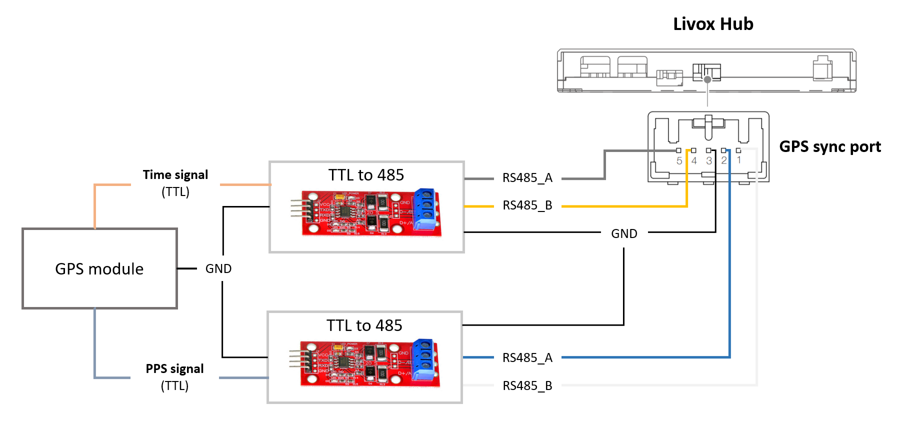
Remarks:
When the Hub uses GPS synchronization, there is no need to configure the SDK software.
2.2.1.2 Livox Converter 1.0
Currently, the default devices using Livox Converter 1.0 include:
- Mid-40
- Mid-100
Hardware connection
Connect the GPS module's time signal (GPRMC) to the PC through the TTL-to-usb module, and connect the PPS signal to the Sync Port of the LiDAR adapter box.
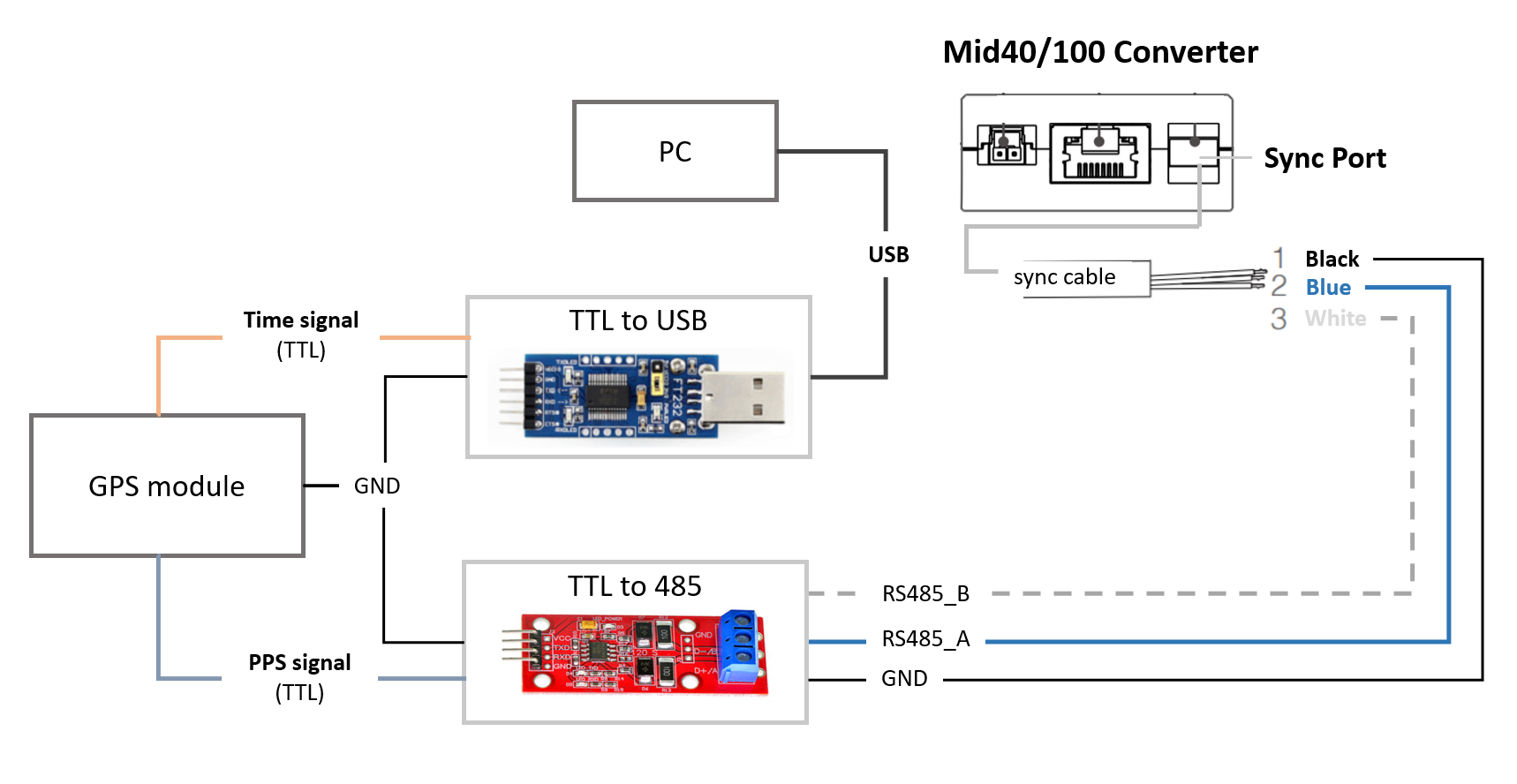
If the PPS output by the GPS module is an RS485 level signal, the TTL to 485 module can be omitted in the above figure.
Software configuration
Since the PC needs to receive the GPRMC data and then send it to LiDAR through the SDK protocol, the product firmware version has the following requirements:
- Mid firmware version: >= v03.07.0000
- SDK version >= v2.1.0
When using ROS driver
-
Connect the hardware correctly according to the above introduction;
-
Check the port name of the usb module connected to the PC, such as
/dev/ttyUSB0,add to the "device_name" of the "timesync_config" in the file livox_lidar_config.json ,and then configure "enable_timesync" to 'true',the baud rate "baudrate_index" can be set to specific value referring to https://github.com/Livox-SDK/livox_ros_driver ;
    "timesync_config": {
        "enable_timesync": true,
        "device_name": "/dev/ttyUSB0",
        "comm_device_type": 0,
        "baudrate_index": 2,
        "parity_index": 0
- Run launch file;
When using SDK only
The following link is a program for receiving and analyzing GPRMC data and sending it to LiDAR through the SDK protocol:
https://github.com/Livox-SDK/Livox-SDK/tree/master/sample_cc/lidar_utc_sync
2.2.1.3 Livox Converter 2.0
Currently, the standard equipments using Livox Converter 2.0 in the box include:
- Horizon
- Tele-15
Hardware connection
Connect the GPS module's time signal (GPRMC) to the PC through the TTL-to-usb module, and connect the PPS signal to the Sync Port of the LiDAR adapter box.
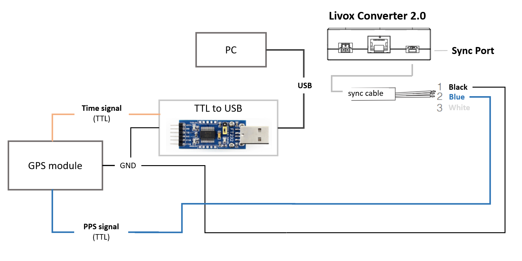
Software configuration
Since the PC needs to receive the GPRMC data and then send it to LiDAR through the SDK protocol, the product firmware version has the following requirements:
- Horizon firmware version: >= v06.06.0000
- Tele-15 firmware version: >= v07.09.0000
- SDK version >= v2.1.0
When using ROS driver
-
Connect the hardware correctly according to the above introductions;
-
Check the port name of the usb module connected to the PC, such as
/dev/ttyUSB0, add to the "device_name" of "timesync_config" in the file livox_lidar_config.json ,and then set "enable_timesync" to 'true',baud rate "baudrate_index" can be set to specific value referring to https://github.com/Livox-SDK/livox_ros_driver ;
    "timesync_config": {
        "enable_timesync": true,
        "device_name": "/dev/ttyUSB0",
        "comm_device_type": 0,
        "baudrate_index": 2,
        "parity_index": 0
- Run launch file;
Using SDK only
The following link is a program for receiving and analyzing GPRMC data and sending it to LiDAR through the SDK protocol:
https://github.com/Livox-SDK/Livox-SDK/tree/master/sample_cc/lidar_utc_sync
2.2.3 Status check
- By viewing the timestamp_type data in the point cloud data packet header, the point cloud data protocol: https://github.com/Livox-SDK/Livox-SDK/wiki/Livox-SDK-Communication-Protocol
If timestamp_type is 3, it means that the device is in GPS time synchronization:
| timestamp_type | data_type | time type |
|---|---|---|
| 3 | UTC(8 Bytes) | UTC time format |
UTC time format:

- Or in the Livox Viewer host computer, check the Settings option, the Sync State in the figure below indicates that the Hub is using GPS synchronization.
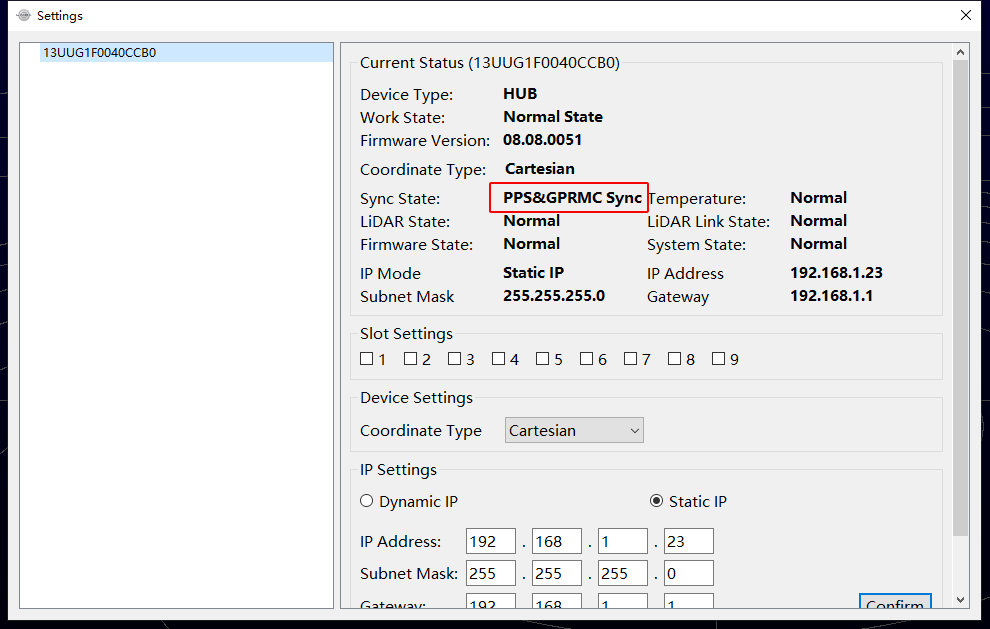
2.2.3 Precautions
- Normally, the GPS module can output the PPS signal and time signal normally after receiving the GPS signal. When in use, you need to ensure that the GPS signal is stable;
- Currently the time signal only supports the two formats: GPRMC and GNRMC;
- 1 us level accuracy
2.3 PPS
Due to the complexity of this usage, users are not recommended to use this synchronization method
Every time Livox LiDAR receives the rising edge of the PPS signal, it will set the point cloud time at the current moment to 0, and then restart timing until the next PPS pulse arrives. We can use this feature to realize the synchronization of the PPS pulse to the LiDAR time.
The following is the pseudo code to implement this process:
// PPS Time Synchronization
static uint64_t lidar_time_last;
static uint64_t lidar_time_real;

// 1. Read the PPS rising edge time, Unit is nanosecond.
uint64_t pps_time_ns = get_pps_rising_nsecond();
// 2. Read LiDAR point time, Unit is nanosecond.
uint64_t lidar_time = get_lidar_pack_time();
// 3. Update real time.
if (lidar_time < lidar_time_last)
{
    //LiDAR time jump indicates the generation of PPS rising edge.
    lidar_time_real = pps_time_ns + lidar_time%(1000000000);
}
else
{
    lidar_time_real += lidar_time - lidar_time_last;
}
//Update history
lidar_time_last = lidar_time;
Remarks:
Users need to obtain the time information of the rising edge of the PPS through other methods, corresponding to the get_pps_rising_nsecond() interface in the above code.
Appendix
Configure PTP master clock
Address: http://linuxptp.sourceforge.net
Download, compile and install:
git clone http://git.code.sf.net/p/linuxptp/code linuxptp
cd linuxptp
make
sudo make install
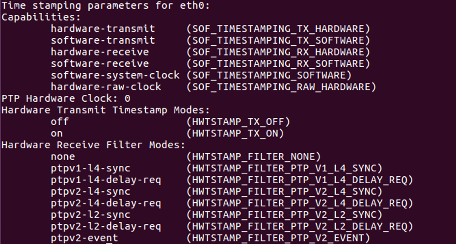
If you want ptp4l to work normally, you need the system's Linux kernel version 3.0 or later. Use the following command to check whether the network card supports the software/hardware timestamp function (for example: query the status of the network card'eth0').
ethtool -T eth0
In the example below, it shows that the eth0 network card supports hardware time stamping.
In the example below, the wlan0 network card does not support hardware and software timestamps, linuxptp/ptp4l cannot work normally.

Run the following command to enable the master clock function of ptp4l:
sudo ptp4l -i eth0 -l 6 -m
If the Sync Message data appears in the network, it means that the master clock function of the ptp4l program is operating normally:
You can also use the following command to make sure that PTP hardware clock is synchronized to system clock:
For more details of the usage, please refer to the phc2sys link
sudo phc2sys -c eth0 -s CLOCK_REALTIME -O 0
After completing the above steps, the LiDAR time and the PC system time can be synchronized through ptp4l.